BNC connector is a connector used for coaxial cable, used for radio frequency signal transmission. Mainly used for coaxial analog cameras, SDI digital cameras, DVR video input/video output and other interfaces. According to the appearance, it is generally divided into two types: male and female.
BNC, the full name is Bayonet Nut Connector (Bayonet Nut Connector, this name vividly describes the shape of this connector), also known as British Naval Connector (British Naval Connector, may be the earliest use of this connector in the British Navy) or Bayonet Neill Concelman (Neill Concelman bayonet, named after its locking method and its inventor, Paul Neill of Bell Labs and Carl Concelman, an engineer from Amphenol.)
BNC connectors are available in 50 ohm and 75 ohm versions. When the 50 ohm connector is connected with other impedance cables, the possibility of transmission errors is less. Connectors of different versions are compatible with each other, but if the cable impedance is different, the signal may reflect. Usually BNC connectors can be used at 4GHz or 2GHz.
https://www.holanvision.com/wp-content/uploads/2021/07/holan.png00Rachelhttps://www.holanvision.com/wp-content/uploads/2021/07/holan.pngRachel2021-12-08 16:16:592021-12-08 16:17:00Video security camera interface
In a computer system, bit is the smallest unit of data storage in the computer, representing binary bit. A binary bit can represent 0 and 1 states.
At the same time, the computer stores and interprets information in bytes, and stipulates that a byte is composed of eight binary bits, that is, one byte is equal to eight bits (1byte = 8bit).
The video rate of a camera is the number of data bits transmitted per unit time. Generally, the unit we use is Kbps, that is, k bits per second, how many kilobits per second. For example, 3000kbps, that is, 3000kbits per second, that is, 375 bytes.
In hard disk storage, theoretically, 1TB = 1024gb, 1GB = 1024MB, 1MB = 1024KB.
But in fact, for convenience, manufacturers such as hard disk storage industry define 1TB = 1000GB, 1GB = 1000MB, 1MB = 1000KB. In addition, some space in the hard disk will be occupied by firmware program, so the actual size of 1TB hard disk is 931GB.
Computing method
Well, with the above knowledge, let’s calculate the size of the surveillance video, that is, the size of the video file per unit time multiplied by the time. Unit time (s) file size (byte) = bitstream (BPS) ÷ 8. 24 hours a day video file size = (bitstream ÷8) × 60 × 60 × 24。
For example, for a 1080p, H.265 encoded network camera, the general reference code stream is 2000kbps, then the hard disk space required for this camera to record 24 hours a day is 2000 ÷ 8 × 60 × 60 × 24=21.6GB。 If the bitstream is 1000kbps, the video file size of one day is 10.8GB, the bitstream is 5000kbps, and the file size is 54gb. In order to facilitate the fast calculation, we can roughly remember that the bitstream value (kbps) × 100 is the amount of hard disk space (GB) occupied by the video 24 hours a day, which is convenient for memory and fast for calculation. Of course, if you need accurate data, you can calculate according to the above formula.
Furthermore, many security product service providers now provide their own online video hard disk storage space calculation tools. The calculation methods and principles are basically based on the above analysis. Some options include H.265/H.264 encoding, resolution and other options. In fact, through these options, we can determine the bit stream value of the built-in camera step by step. If we know the bit stream of the camera, we don’t have to be so troublesome.
https://www.holanvision.com/wp-content/uploads/2021/07/holan.png00Rachelhttps://www.holanvision.com/wp-content/uploads/2021/07/holan.pngRachel2021-10-16 20:57:522021-10-16 20:58:16How to calculate the file size of security video
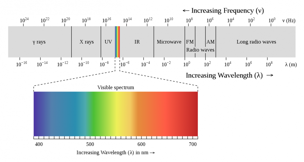
Light is an electromagnetic wave with different frequencies, and light of different frequencies will have different colors.
Human eyes can see objects because they can emit light or reflect light (the light that human eyes can perceive). But the light in nature is only part of what the human eye can perceive (see). Through research, we found that the human eye can fully see light with a wavelength between 780 and 400 nm, while the light with a wavelength between 880 and 780 nm can also be slightly perceived by the human eye. The visible light (the light that the human eye can see) is red, orange, yellow, green, blue, and indigo purple. White light is the synthesis of all these spectra.
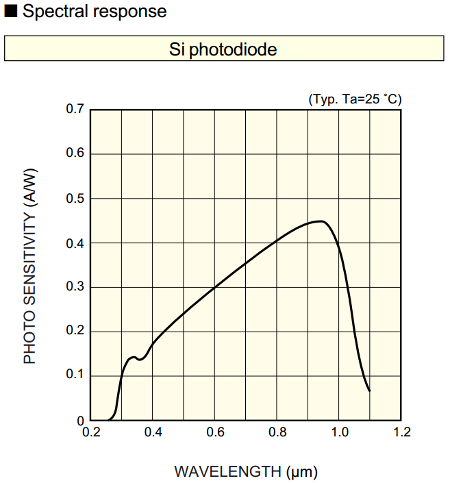
Similar to the human eye, the image sensor in the camera can also perceive light of a specific wavelength. The photosensitive element of CCD or CMOS is generally composed of silicon. The following figure shows the spectral response curve of silicon:
From the spectrum of silicon, we can see that, in addition to sensing visible light at 780-400nm, silicon is most sensitive to light at 700-1000nm. The range of 800-1000nm is infrared light. Because of this physical characteristic, CCD/CMOS cameras can better perceive infrared light, and human eyes are not sensitive to infrared light. In environments lacking visible light (such as night), security cameras often use infrared supplementary light, which will not Human eyes cause light pollution and also play a relatively concealed effect.
Infrared light
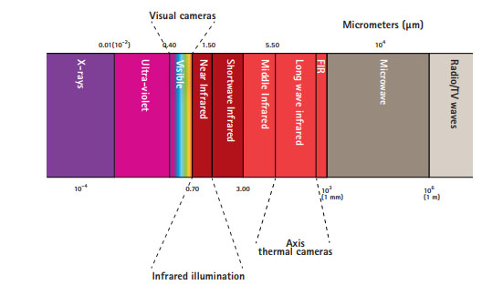
Infrared (IR) is an electromagnetic wave with a wavelength between microwave and visible light, and its wavelength is between 760nm and 1000nm.
According to different detection needs, we can subdivide the infrared light into:
Near infrared (NIR): The wavelength range is 700 to 1000 nm (from the range that the human eye cannot detect to the range that silicon can respond to);
Short-wave infrared (SWIR): The wavelength range is 1000 to 3000 nm (from the cut-off frequency of silicon to the cut-off frequency of the atmospheric infrared window);
Mid-wave infrared (NWIR): The wavelength range is 3000 to 5000 nm;
Long wave infrared (LWIR): The wavelength range is 8000 to 12000 or 7000 to 14000 nm;
Far infrared (FIR): The wavelength range is 12000 to 30000 nm.
Near infrared (NIR) is just beside the visible section of the human eye, while medium and long-wave infrared (MWIR, LWIR) and far infrared (FIR) are farther than the visible section of the human eye.
Fill light
Infrared
In the early development of security cameras, Japanese and Korean brands such as SONY, Samsung, Panasonic, and Sharp mainly focused on the performance of cameras such as WDR and low-light. There was not much research and development on infrared technology. In the early days, SONY and Panasonic did not have infrared security cameras. The reason will be explained in detail in the section on the problem of infrared lamps. Security camera manufacturers in Taiwan and China have seen the development prospects of infrared technology in the application of security cameras, and have successively introduced infrared cameras and IR-CUT technology, which have produced very good market effects.
As mentioned earlier, security cameras generally use near-infrared to fill light when the visible light is insufficient. This is because the photosensitive element of CCD/CMOS is made of silicon, and silicon is very sensitive to near-infrared. At the same time, human eyes are not sensitive to near-infrared, which can avoid light pollution and be more concealed during night vision. Security cameras generally use 850nm and 940nm infrared fill light, and 850nm uses more.
As mentioned earlier, the human eye can slightly perceive the light from 880 to 780nm, so the human eye can slightly see the infrared light of 850nm (the red bright spot is visible to the human eye), while the infrared of 940nm is completely invisible, so the 940nm infrared The concealment of the camera is better. But it is a pity that the sensitivity of CCD/CMOS image sensors to 940nm light is much worse than that of 850nm. For better night vision, most infrared cameras now use 850nm infrared lamps.
The figure below shows how the CCD/CMOS image sensor responds to different light.
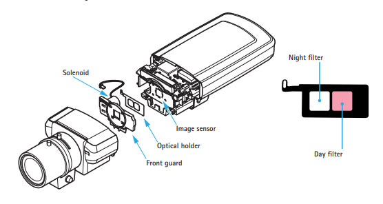
Filter The filter is made of plastic or glass with special dyes. The red filter can only let red light pass, and so on. The transmittance of the glass sheet is originally similar to that of air, and all colored light can pass through, so it is transparent, but after dyeing the color, the molecular structure changes and the refractive index also changes, which changes the passage of certain colored light.
Image sensor NIR technology
Although silicon can sensitively respond to near-infrared, in order to achieve better infrared night vision, CMOS manufacturers continue to improve the near-infrared imaging effect and sensitivity of image sensors through technology. NIR technology is the focus and core technology of image sensor manufacturers.
Infrared light development
Infrared technology is divided into passive infrared thermal imaging sensing and active infrared light emission. Security cameras generally use active infrared technology.
On the whole, the development of infrared fill light technology for security cameras has gone through 3 generations.
The first generation, traditional LED lights, in-line. A single light-emitting diode is used for packaging with epoxy resin material, and the chip size is generally between 12mil-16mil. The packaged size is generally φ5 or φ8. Condensing light is achieved through the reflective bowl in the chip and the lens on the top of the encapsulated epoxy resin. The lens can be made into different angles to match the angle of the camera lens to achieve the best effect.
Main feature:
The single power is small. The chip size is 12-16mil, the current of a single lamp is very small, and the power is very low. In order to achieve good results, generally increase the number of particles. The number of common particles is generally 24-56, and the irradiation distance ranges from 10 meters to 40 meters. If you want to illuminate farther, it is difficult to use this LED light.
The light decays fast. The epoxy resin lens is easy to break when exposed to heat, and the infrared light is easily refracted back through the broken surface. With the passage of time, more and more fractured surfaces, more and more infrared light is refracted back, and very little can be penetrated. This is the main reason for the fast attenuation and short life of traditional LED lights.
Poor heat dissipation. Traditional LED lights are energized through two pins, emit light, and generate heat at the same time, and the thermoelectricity is not separated. The surrounding temperature is higher, which reduces the life of electronic components. However, if a single LED lamp is broken, it will not affect other LED lamps to continue working.
https://www.holanvision.com/wp-content/uploads/2021/07/holan.png00Rachelhttps://www.holanvision.com/wp-content/uploads/2021/07/holan.pngRachel2021-10-03 12:45:322021-10-12 14:15:21The development of infrared (fill light) technology for security cameras
As mentioned in the previous chapter(Security camera classification), according to the different output video signals, we can divide security cameras into three categories: analog, digital, and network. Different types of cameras have different internal components and mechanisms, such as analog and digital cameras, which only have image processing and no video image encoding.
The internal structure and composition of the camera are introduced here for the sake of simplicity. On the whole, we can divide the interior of the security camera into three major parts: image capture, video image processing and coding, and signal output .
Image capture
The image acquisition of the camera is mainly completed by the lens and the image sensor on the chip. The light passes through the lens and enters the sensor on the chip. The sensor is responsible for converting the received optical signal into an electrical signal, and then handing it over to the subsequent unit on the chip for processing.
The focal length of the lens (fixed focus, zoom), aperture, quantity (multi-lens used in multi-eye cameras), effective pixels, etc. will affect the signal sent to the sensor, thereby affecting the final imaging effect.
After the light reaches the sensor, it first performs the preliminary processing of converting the light signal into an electrical signal. The main performance parameters of sensor include target size, effective pixels, low-light performance and so on. These will also affect the final imaging effect. For the parameters and performance of the sensor, please refer to Security image sensor, Starvis full-color camera technology, Wide dynamic function of security camera and other chapters.
Image processing, video coding
The electrical signal converted by the sensor needs to be delivered to the processor on the camera chip for image processing, video encoding and other operations.
The processor is a very general term, similar to the CPU of a computer or mobile phone. For cameras that output analog or digital signals, the processor here mainly refers to ISP, that is, Image Signal Processor.
The main work of ISP includes:
DEMOSAIC, translated into Chinese is anti-mosaic. Each pixel signal output by the sensor contains only one color data among R, G, and B. This kind of data is bayer data, which is commonly referred to as RAW data. Obviously, the color information reflected in RAW data is not true color information. DEMOSAIC’s job is to calculate the true color represented by each pixel through an interpolation algorithm, that is, to convert the Bell image into a true color image.
3A control. It is a collective term for Auto Focus (AF), Auto Exposure (AE) and Auto White Balance (AWB). This is the core part of ISP comparison, and the quality of processing is directly related to the final output image effect. ISP can realize auto-focusing through various auto-focusing algorithms such as CONTRAST AF, PDAF, LASER AF, etc., so that the target can be clearly imaged on the sensor. Exposure mainly affects the brightness of the image. ISP can control the degree of exposure to make the image brightness appropriate. White balance is related to color temperature and is used to measure the color authenticity and accuracy of an image. The automatic white balance function strives to accurately restore the original color of the target in various complex scenes.
Gamma correction. The response of the sensor to light is different from the response of the human eye to light. Gamma correction is to make the image look in line with the characteristics of the human eye.
Image cropping. That is, changing the size of the image can be used to output images of different resolutions. For example, the original resolution of 2048*1536, 4:3 is cropped to 2304×1296, and the resolution of 16:9 is more in line with the widescreen visual effect. Or a 5MP sensor, and it can also support different resolutions such as 4MP, 3MP, and 1080P.
Intelligent Algorithm. Used to identify specific targets, such as face recognition, human shape recognition, license plate recognition, etc. ISP uses various intelligent algorithms to accurately identify specific targets. Of course, in the network camera, the intelligent algorithm can also be built into the encoding chip. At the same time, intelligent algorithms and structured data functions can be placed in the sensor. For example, Sony’s AI sensor (SONY IMX500/501) has achieved direct output of structured data.
Dynamic Range. The dynamic range is the light and dark range of the image. ISP processing makes the dark part of the target image not under-exposed, and the bright scene is not over-exposed. In addition to the dynamic range processing supported by the ISP, the image sensor also needs to support the dynamic range (HDR) function. For details, please refer to the “Wide dynamic function of security camera” section.
The image is stable and anti-shake. The main function is to prevent the image from being blurred due to the slight shaking of the camera.
In addition to the above work and processes, ISP’s functions also include noise reduction, contrast, saturation, sharpness, etc. Due to the technical accumulation of different manufacturers, different solution providers, and differences in algorithms, the image effects of cameras with exactly the same hardware solution will be different.
The analog optical signal is converted into a digital signal by the sensor, and after ISP processing, it can directly output the image of the digital signal, such as an SDI camera. It can also undergo digital-to-analog conversion again to convert the digital signal into an analog signal for output, such as analog SD cameras with traditional cvbs signals, and high-definition analog cameras such as AHD/CVI/TVI/XVI.
On the other hand, the digital signal can also be encoded and output and transmitted through the network, that is, a network camera. The encoding at this time requires a special encoding chip to complete. It should be noted that most of the current encoding chips have integrated ISP functions.
For processors with video encoding functions, we generally call them CPU, DSP or SOC. Strictly speaking, there is a difference between the three. But for the processing chip of a security camera, it is not bad to call it CPU, DSP or SOC. In order to unify and follow the manufacturer’s customary naming, we call the processors that support video encoding functions SOC.
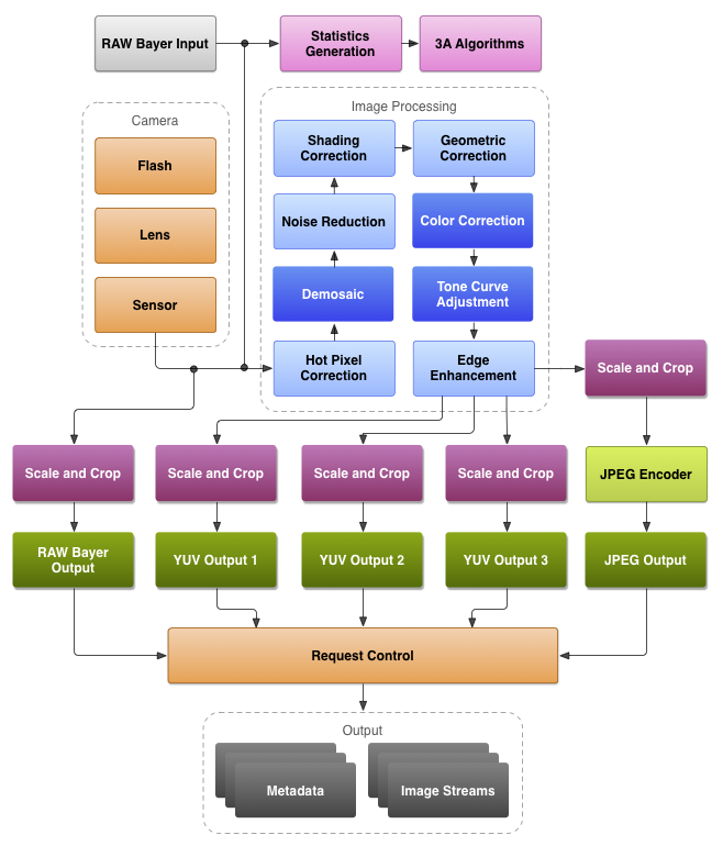
SOC, or system on chip, can be regarded as a three-in-one processor, ISP, and encoding chip. The following is a block diagram of a typical security video encoding chip:
From this we can see that its main structure is divided into Quad Core Arm® Cortex®-A53 (ie processor), Image Signal Processor (ISP), Video Codec. The front end can be connected to sensor, audio, alarm and other equipment. In order to support the operation of the system, there are running memory and internal storage. It can directly extend WiFi/4G, SD card storage, etc., and can output analog/digital video, audio, alarm, network, serial port (485, 232) and other signals.
The core function of SOC is video encoding. For example, the typical SOC chip provided above supports three video encoding methods: H.264, H.265, and MJPEG. Related concepts of video coding have a detailed introduction about video coding in the section, so I won’t go into details here.
At this stage, with the development of chip technology and AI smart algorithms, more SOC manufacturers have built smart functions into SOC chips, which are more, more powerful and more scalable than those built into ISP.
Signal output
The video signal, audio or other signals processed by ISP or SOC can be output as analog, digital and network signals as required.
Analog signal. After the electrical signal of the video image is processed by the ISP, it is converted into an analog signal by D/A and output through the BNC connector. Common analog video signals include standard definition CVBS, high definition AHD/TVI/CVI/XVI, etc. Theoretically, high-definition AHD/TVI/CVI/XVI signals can transmit audio, alarm, and control signals while transmitting video signals.
Digital signal. After the electrical signal of the video image is processed by the ISP, the digital signal is no longer directly output through D/A conversion. The common output interface can be a BNC header or an HDMI interface. Such cameras are mainly SDI cameras. The HDMI interface can transmit audio while transmitting digital video signals.
Internet signal. The digital signal is encoded by the encoding chip, and then can be transmitted through the network. This kind of network signal needs to go through the corresponding decoding to display the video image. Common decoding equipment and methods include the corresponding computer client, NVR, video decoder, network matrix, etc. On the other hand, audio, alarm, RS485 and other signals can also be encoded together with the video signal and then transmitted over the network.
https://www.holanvision.com/wp-content/uploads/2021/07/holan.png00Rachelhttps://www.holanvision.com/wp-content/uploads/2021/07/holan.pngRachel2021-09-28 22:23:332021-10-02 14:50:46The internal structure of the security camera
Transmission is signal propagation through various means (via media such as wire, coaxial cable, microwave, optical fiber, or radio frequency, etc.). There are two points in this. One is the means of transmission, that is, the transmission medium used, and the other is the signal to be transmitted.
The signals that need to be transmitted in the security system mainly include power, video, audio, alarm I/O, control signals, etc.
The main transmission methods and media are: coaxial cable, twisted pair, optical fiber, wireless (Wi-Fi and 4G, etc.), microwave, satellite, etc.
The details are described below.
Transmitted signal Power signal Security cameras generally use DC12V power supply, some dome cameras use AC24V power supply, and some home Wi-Fi smart cameras use DC5V power supply.
Hard disk video recorders DVR/NVR, ordinary switches generally use DC12V power supply or directly use AC220V power supply.
The POE switch uses AC48-52V power supply.
Back-end equipment, such as various servers, matrixes, and TV walls, generally use AC220V power supply.
Video signal As mentioned in the article on the classification of security cameras, according to the different output signals, cameras can be divided into three types: analog, digital, and network.
An analog signal refers to a signal whose mathematical form is a continuous function in the time domain, which corresponds to a digital signal.
The analog video signal transmits a set of brightness and chrominance data of a video image that changes over time. Expressed by a digital function, time is the independent variable and the signal itself is the dependent variable. This function takes values continuously on the time axis.
If only sampling at a fixed time node, such a signal is called a discrete-time signal, and a finite word length is used to represent the value of all sampling points. Such a discrete-time signal is called a digital signal.
Conceptually, a digital signal is a quantized discrete-time signal, and a discrete-time signal is an analog signal that has been sampled.
Because the value is continuously taken, it is obvious that the analog signal is more susceptible to noise interference. At the same time, almost all transmission media, such as coaxial cables, radio waves, optical fibers, etc., can be applied to digital or analog signals, but digital signals can use these media more effectively than analog signals.
Network signals, to be precise, should be called encoded digital signals, which are transmitted through a computer network, and they are still digital signals.
Audio signal Sound is a sound wave generated by vibration, which is transmitted through a medium (gas, solid, liquid) and can be sensed by human or animal auditory organs.
The frequency of sound is generally expressed in Hertz, recorded as Hz, which refers to the number of periodic vibrations per second. The decibel is a unit used to express the intensity of a sound, denoted as dB.
The audio signal is the same as the video signal, and the audio is simulated by the analog signal, so the audio signal can be transmitted through the same medium as the video signal. In particular, audio can also be encoded like video signals and transmitted over the network. For more details, please refer to the article on Audio Function in Network Camera.
Control signal The control signals in security mainly include RS-485 pan/tilt control signal and RS-232 serial port signal.
RS-485 uses the voltage difference between the two ends of the cable to represent the transmission signal, and the different voltage differences are respectively identified as logic 1 and logic 0. It is valid when the voltage difference between the two ends is at least 0.2V and above. Any difference not greater than 12V or not less than -7V is considered correct for the receiving end.
RS-485 only specifies the electrical characteristics of the receiving end and the transmitting end. It does not specify or recommend any data protocol. (In the early use of the PTZ control function, you need to set the address code, protocol, and baud rate of the dome camera. Now the requirements are not so strict, and any protocol or baud rate may be able to control the PTZ equipment normally)
RS-485 is recommended to be used in point-to-point networks, linear and bus types, not star or ring networks. If you must use a star network, you need to use a special RS-485 splitter/repeater.
RS-232 is an interface standard for serial data communication formulated by the Electronic Industries Alliance (EIA), and is widely used in computer serial interface peripheral connections.
In the RS-232 standard, characters are transmitted serially in a serial bit string one after another. The advantage is that there are fewer transmission lines, simple wiring, and a longer transmission distance.
The cables and connectors used by RS-232 may be 3 to 25 pins, and the typical application is 4 to 6 pins.
RS-232 serial communication requires multiple settings in the software settings. The most common settings include baud rate, parity, and stop bit.
Alarm I/O signal The alarm input and output signals are generally high and low levels or switch values. Its essence is a digital circuit.
The main problem studied in digital circuits is the logical relationship between the state of the output signal (“0” or “1”) and the input signal (“0” or “1”), that is, the logical function of the circuit. (Under positive logic, “0” is low level, “1” is high level, and there is no clear boundary between high and low levels)
There is a detailed description of the alarm input and output interface and signal in the article on the external interface of the camera, which will not be repeated here.
Transmission equipment and media For the requirements of various cables used in security, please read the article Cables used in security. Here mainly talk about some special transmission functions and others.
Power line transmission In addition to transmitting power signals, power lines can also transmit video signals, network signals, etc., with the help of power carrier technology.
Power line carrier communication is PLC, which is the abbreviation of English Power line Carrier. Power line carrier is a unique communication method of power system. Power carrier communication refers to the technology that uses existing power lines to transmit analog or digital signals at high speed through carrier waves. The biggest feature is that there is no need to re-establish the network, as long as there are wires, data can be transmitted.
When using power lines to transmit video signals, when network signals, you need to use the corresponding power line bridge, similar to a wireless bridge, one transmitter and one receiver, or many-to-one use.
Power line carrier transmission problems:
It can only be transmitted within the area of a distribution transformer; It can only be transmitted on single-phase power lines; The power line causes a high reduction in the carrier signal; The power line has inherent impulse interference. Because of the above drawbacks, power line transmission technology is only a useful supplement, and it is difficult to apply and develop on a large scale.
Coaxial cable transmission Similar to power carrier technology, coaxial cable can also be used to transmit network signals. This technology is called EOC (Ethernet Over Cable).
Similarly, EOC transmission also requires the help of corresponding bridges, one for transmitting and one for receiving, or many-to-one use.
The main problems of EOC: poor anti-interference ability, short transmission distance, and numerous standards. More importantly, network bandwidth has long been popularized, and the market stock using coaxial cable TV is becoming less and less. Therefore, it is less and less necessary to use EOC to transform the network.
Twisted pair transmission Twisted pair is a kind of cable that is twisted into a spiral by two insulated double wires covered with plastic insulation material and copper cables inside.
In the two wires, the current induced by each wire is almost equal. The twisting of the two wires ensures that the average distance between the two wires and the source of interference is the same, and the effects are the same. The noise therefore generates a common-mode signal, which can be eliminated at the receiver only by detecting the differential signal.
Therefore, the twisted pair can reduce the attenuation in signal transmission, reduce crosstalk and noise, and improve the ability to suppress external electromagnetic interference.
Twisted-pair cables used to be mainly used to transmit analog signals, but they are now also suitable for digital signal transmission and belong to the transmission medium of information communication networks.
The use of twisted pair cables to transmit analog video requires the use of corresponding twisted pair transmitters (one receiver and one transmitter are used in pairs). When used to transmit digital network signals, use RJ-45 connectors, commonly known as crystal heads.
Multiple network cameras, network devices are transmitted through network cables, and they are gathered together using switches. For related introductions to switches, please refer to the articles on Switch Selection in Security Video Surveillance and PoE Power Supply.
Twisted pair specifications EIA/TIA defines model specifications based on different qualities for twisted-pair cables.
Model Specification CAT-1 is mainly used for voice transmission CAT-2 transmission frequency is 1MHz, the highest transmission rate is 4Mbps CAT-3 transmission frequency is 16MHz, the highest transmission rate is 10Mbps CAT-4 transmission frequency is 20MHz, the highest transmission rate is 16Mbps CAT-5 transmission frequency is 100MHz, and the highest transmission rate is 100Mbps CAT-5e has low attenuation and low crosstalk CAT-6 transmission frequency is 250MHz, transmission speed is 1Gbps, standard outer diameter is 6mm CAT-6A transmission frequency is 500MHz, transmission speed is 10Gbps, standard outer diameter is 9mm CAT-6e transmission frequency is 500MHz, transmission speed is 10Gbps, standard outer diameter is 6mm CAT-7 transmission frequency is 600MHz, transmission speed is 10Gbps CAT-8 transmission frequency is 2000MHz, transmission speed is 40Gbps
Fiber optic transmission Whether it is a coaxial cable or a twisted pair cable, the transmission distance is limited. When a wired transmission is required for several kilometers or tens of kilometers, optical fiber is required.
Optical fiber, the full name of optical fiber (Optical fiber), is a fiber made of glass or plastic, and a light transmission tool that uses the principle of total internal reflection to transmit light in these fibers.
The tiny optical fiber is encapsulated in a plastic sheath so that it can be bent without breaking. Generally, the transmitting device at one end of the optical fiber uses a light-emitting diode or a laser beam to send light pulses into the optical fiber, and the receiving device at the other end of the optical fiber uses a photosensitive component to detect the pulses. Cables containing optical fibers are called optical cables. Because the transmission loss of information in optical fiber is much lower than that of electricity in wire transmission, and because the main production material is silicon, it has a large reserves and is easier to mine, so the price is very cheap, which promotes the use of optical fiber as long-distance information Transmission medium.
In addition to fiber-optic cables, fiber-optic data transmission requires the use of fiber-optic transceivers, which can be used in pairs for receiving and transmitting data. The optical fiber transceiver function can also be built into the switch, that is, the optical fiber interface (SFP) of the switch to realize the transmission of optical signals.
The use of light-emitting diodes to transmit multiple beams of light is called multimode fiber. It is a single-mode fiber that uses a laser to emit a single beam of light. Single-mode and multi-mode fibers cannot be mixed, and the corresponding optical transceivers cannot be mixed.
Generally, we call the optical fiber equipment that transmits network digital signals an optical fiber transceiver, and the optical fiber equipment that specializes in transmitting video signals is called an optical transceiver.
Fiber optic connector Common fiber optic connectors are divided into FC and SC. FC is the Ferrule Connector round with thread, which is mostly used on patch panels. SC is the Snap-in Connector card-connected square type, which is mostly used in routers and switches.
All of the above are wired transmission, and the wireless transmission is introduced below. In any case, the stability and reliability of wireless transmission are worse than wired transmission, and wireless transmission only exists as a useful supplement to wired transmission.
Wireless transmission Wi-Fi In theory, security equipment that uses wired network transmission, such as network cameras, DVRs, NVRs, etc., can expand the wired network to wireless Wi-Fi by adding a wireless Wi-Fi network card.
Wireless bridge The transmission distance of wireless Wi-Fi is generally limited. For special needs, we can use high-power wireless bridges to wirelessly transmit network digital signals or video signals over a long distance.
Wireless bridges are also used in pairs, one for receiving and one for sending. Of course, it can also be used in many pairs. The transmission distance can be several kilometers to dozens of kilometers. When performing wireless transmission, there should be no obstacles between the bridges. When the distance is long, the antenna angle between the bridges needs to be adjusted to achieve the best wireless transmission effect.
Microwave transmission Microwave communication refers to a comprehensive technology that transmits signals using microwaves with frequencies between 0.3 GHz and 300 GHz (wavelengths between 0.1 mm and 1 meter) as carriers. The millimeter wave band used in 5G communications is microwave.
Microwave communication is a communication that directly uses microwave as a medium, and does not require a solid medium. Microwave transmission can be used when there is no obstacle within a straight line distance between two points. Generally, a parabolic antenna is used to transmit and receive microwave signals.
Microwave communication has good disaster resistance performance, and is generally not affected by natural disasters such as floods, wind disasters, and earthquakes. However, microwaves are transmitted through the air and are susceptible to interference. The same frequency cannot be used in the same direction on the same microwave circuit. Therefore, the microwave circuit must be constructed under the strict management of the radio management department.
Satellite transmission Radio communication uses electromagnetic waves to transmit signals. These waves are transmitted in a straight line, so they will be blocked by the curved surface of the earth. Therefore, communication satellites can be used to transmit signals on the surface of the earth to achieve long-distance communication on the ground.
The satellite orbit is high above the ground, the antenna beam can cover a large area of the earth, and the radio wave propagation is not restricted by the terrain. The satellite is equipped with a transponder composed of receiving and transmitting equipment, which amplifies and shifts the frequency of the received signal and transmits it to the ground.
https://www.holanvision.com/wp-content/uploads/2021/07/holan.png00Rachelhttps://www.holanvision.com/wp-content/uploads/2021/07/holan.pngRachel2021-09-12 16:29:242021-09-27 16:33:49Transmission in Surveillance Security
AI is everywhere. Artificial Intelligence AI–>Machine Learning ML–>Deep Learning DL–>Computer Vision CV, and the realization of AI intelligence functions in security mainly rely on computer vision to realize the understanding and recognition of images, speech and text. The AI function is mainly affected by the three factors of algorithm, computing power, and big data.AI function AI functions in security include smart functions based on front-end cameras, smart functions based on back-end central platforms, or cloud-side integration. Among them, based on the AI intelligent function of the front-end camera, there is a new concept, software-defined camera, that is, whether the intelligent function of the camera is mainly determined by software (SDC) or hardware, which has caused heated discussions and debates in the industry. My point of view: The market demand is determined, not by technology.
Common AI functions in the security field are divided into the following 4 categories:
Human body analysis: face recognition, posture recognition, human body feature extraction, etc.; Vehicle analysis: license plate recognition, vehicle recognition, vehicle feature extraction, etc.; Behavior analysis: target tracking and monitoring, abnormal behavior analysis, etc.; Image analysis: video quality diagnosis, video summary analysis, etc. If it is further subdivided, there are currently these smart functions:
Humanoid, animal detection Face detection Snapshots, attributes, glasses, hairstyle, gender, facial expressions, etc. People and traffic statistics Vehicle, pedestrian road violation Multi-dimensional perception (human expression, car, behavior analysis) Video structured General smart function Behavior analysis: cross-border detection, area intrusion detection, entry/exit area detection, wandering detection, people gathering detection, fast motion detection, parking detection, item left/take detection Anomaly detection: scene change detection, audio anomaly (audio steep rise / steep fall detection, audio presence or absence detection), virtual focus detection Statistics: over-line counting function Vehicle inspection Support license plate capture, color, model, main brand, sub-brand, year model, etc. identification, machine non-human recognition, detection of forward or reverse driving vehicles, pedestrians and non-motor vehicles, automatic identification of vehicle license plates, you can capture no license plate Pictures of vehicles. Computing power The computing power is the computing power of the processor. The general unit is TOPs, which is the abbreviation of Tera Operations Per Second. 1TOPs means that the processor can perform one trillion operations (10^12) per second.
Corresponding to GOPs (Giga Operations Per Second), MOPs (Million Operation Per Second). 1GOPs means that the processor can perform one billion times per second (10^9) Operation, 1MOPs means that the processor can perform one million operations (10^6) per second.
In some cases, the power consumption of the processor is also an important factor to consider. Therefore, TOPs/W is also used as a performance index to evaluate the computing power of the processor. TOPs/W is used to measure how many trillion operations the processor can perform under the condition of 1W power consumption.
The computing power and power consumption of some common processors can refer to this statistic: Neural Network Accelerator Comparison
Lightspeeur2803 has an energy efficiency ratio of 24Tops/W, which is currently the AI chip with the highest energy efficiency ratio. Google’s TPU3.0 computing speed has reached 420TOPs.
In the security chip, Hi3516CV500 reached 0.5TOPs, Hi3516DV300/Hi3516AV300 reached 1.0TOPs, Hi3519AV100 reached 2.0Tops, and Hi3559AV100 reached 4.0TOPs (Huawei used this chip to make a 20TOPs police bayonet camera).
Rockchip’s RV1109 supports 1.2Tops, and RV1126 supports 2.0Tops.
The computing power is mainly determined by the performance of the AI chip. AI chips are mainly divided into four types: traditional CPU, GPU, semi-customized chips, and fully customized chips.
AI chip classification
Name Main Manufacturer Features CPU Intel, AMD cannot process calculations in parallel GPU NVIDIA, AMD have powerful parallel computing capabilities and floating-point computing capabilities. The GPU platform is very efficient in algorithm training. However, when processing a single input in inference, the advantages of parallel computing cannot be fully utilized. FPGA Xilinx, Altera programmable array, semi-customized ASIC TPU Google ASIC Tensor Processing Unit, Tensor Processor NPU Cambrian, Apple NPU (Neural Network Processing Unit), Neural Network Processor VPU Intel Vector Processing Unit vector processor BPU Horizon Brain Processing Unit, brain processor BM1680 Bitmain EPU / DPU Wave Computing Deep Learning Processing Unit, the deep learning processor HPU Microsoft Holographics Processing Unit Holographic Image Processor IPU Graphcore Intelligence Processing Unit Algorithm Algorithm (algorithm) is a series of well-defined specific calculation steps in mathematics and computer science. It is often used in calculations, data processing and automatic reasoning. As an effective method, an algorithm is used to calculate a function. It contains a series of clearly defined instructions and can be clearly expressed in a limited time and space.
Mathematicians and logicians in the early 20th century encountered difficulties in defining algorithms, until British mathematician Turing put forward the famous Turing thesis and proposed an abstract model of a hypothetical computer. This model is called a Turing machine. . The emergence of Turing machine solved the problem of algorithm definition, and Turing’s thought played an important role in the development of algorithm.
The core of the algorithm is to create an abstract model of the problem and a clear solution goal. After that, different modes and methods can be selected according to the specific problem to complete the design of the algorithm.
Common algorithms in machine learning include decision tree, random forest algorithm, logistic regression, SVM, naive Bayes, K nearest neighbor algorithm, K mean algorithm, Adaboost algorithm, neural network, Markov and so on.
Different algorithms may be used to solve different problems, or the same algorithm may be used. No certain algorithm is omnipotent, only the scope of application is different. It is important to choose the right algorithm for different scenarios.
There is no distinction between advanced and low-level algorithms. Quick and easy problem-solving is the foundation. Blindly pursuing complex algorithms is sometimes equivalent to “smashing mosquitoes with anti-aircraft guns.”
Big data According to incomplete statistics, there are currently about 225 million surveillance cameras used in all walks of life across the country, and the amount of data generated in a medium-sized city in 90 days is about 36PB. How to use these isolated, disorderly, unstructured data, centralized management, and orderly and selective structured processing will be of extraordinary significance.
At present, a series of projects such as Xueliang Project, Safe City and Smart City have realized video surveillance networking in a certain area and centralized management of video data. These video big data can be used to help establish and train various algorithm models and improve algorithms. At the same time, the improved and optimized algorithm can be quickly added to the project practice and be tested in actual combat.
In the future, we can further cultivate and mine video big data to maximize its value.
https://www.holanvision.com/wp-content/uploads/2021/07/holan.png00Rachelhttps://www.holanvision.com/wp-content/uploads/2021/07/holan.pngRachel2021-08-21 15:22:452021-08-21 15:22:46AI function in security video surveillance
Thunder protection is a systematic project. In addition to various devices themselves, they need to have certain thunder protection and surge protection capabilities. In the engineering design and installation of security systems, attention should also be paid to the thunder protection of equipment and systems.
Thunder hazard Thunder and lightning is a very spectacular sound, light and electrical phenomenon in nature. At the same time, a thunder disaster is also a very serious natural disaster. The thunder damage to the weak current security system and electronic information system is mainly through the following types of thunder:
Direct thunder Direct thunder refers to thunder strikes directly on buildings or thunder protection devices, causing electromagnetic, thermal and mechanical effects. About 3.1 billion thunder strikes occur on the earth every year, and direct thunder strikes account for 1/5–1/6.
The peak voltage of direct thunder can reach tens of thousands of volts or even millions of volts, and the peak current can reach tens of KA or even hundreds of KA, but its duration is usually only a few μs to hundreds of μs, which is huge in terms of instantaneous power. Yes, so it is very destructive.
Inductive thunder Inductive thunder refers to all objects on the ground when a thundercloud comes, especially conductors, due to electrostatic induction, will gather a large amount of thunder with the opposite polarity of the bound charge. After the thundercloud strikes the ground or discharges another thundercloud, The charge in the cloud becomes a free charge, which generates a very high electrostatic voltage (induced voltage), and its overvoltage amplitude can reach tens of thousands to hundreds of thousands of volts. This overvoltage often causes damage in buildings. Wires, poorly grounded metal conductors and large metal equipment discharge and cause electric sparks, which can cause fires, explosions, endanger personal safety or cause harm to various electronic information systems such as security. This is an electrostatic induction mine.
In another case, when a thunder strike occurs, a strong induced electromagnetic field is formed near the passage due to the large rate of change of the thunder current, which causes interference and damage to the electronic equipment in the building. It may also cause the surrounding metal components to generate induced current, generate a lot of heat and cause a fire. This is an electromagnetic induction mine.
Conductive thunder When the outdoor overhead line is directly struck by thunder or induced thunder, the high potential will invade along various cable lines and be transmitted into equipment or buildings. This kind of thunder intrusion will cause harm to electronic information equipment or cause damage in the building. Metal equipment discharges, causing damage.
Thunder protection standard The main organizations for the formulation of thunder protection standards are the Thunder and thunder Protection Technical Committee (TC81) under the International Electrotechnical Commission (IEC), and the corresponding National thunder Protection Standardization Technical Committee (SAC/TC258) under the Chinese Association for Standardization (CAS), and International Telecommunications Union (ITU).
The main thunder protection standards of IEC/TC81 are:
IEC-61024 (thunder protection of buildings) IEC-62305 (thunder Protection) IEC-61643 (low-voltage surge protection device) IEC-1312 (protection of thunder electromagnetic pulse) IEC 61000-4-2 (Electromagnetic compatibility test and measurement technology, electrostatic discharge immunity test). Corresponding to GB/T-17626.2 IEC61000-4-5 (Electromagnetic compatibility test and measurement technology, surge immunity test) ITU-T (International Telecommunication Union Telecommunications Part) K series (anti-interference protection):
ITU-T K.21 (the ability of terminal telecommunication equipment to withstand overvoltage and overcurrent). Corresponding to GB/T-17626.5 ITU-T K.20 (Electromagnetic Compatibility Technical Standard for Telecommunications Switches) IUT-T K.27 (connection structure and grounding in the telecommunication building)
Chinese standards:
GB/T-17626 (Electromagnetic compatibility test and measurement technology) GB50057-2016 (Code for thunder protection design of buildings) GB500174-2017 (Data Center Design Specification) GA173-2002 (thunder Protection Device for Computer Information System) GB50343-2012 (Technical Specification for thunder Protection of Building Electronic Information System) GA267-2018 (Computer Information System Thunder and thunder Electromagnetic Pulse Safety Protection Specification) GB50311-2016 (Code for Design of Generic Cabling System Engineering) YD5078-98 (Technical Regulations for thunder Protection of Communication Engineering Power System) GB/T-9361-2011 (Safety Requirements for Computer Sites) DL/T621-1997 (Grounding of AC electrical equipment) GB/T-19856-2005 (thunder Protection Communication Line). Corresponding to IEC 61663:2001 GB50689 (Code for thunder Protection Grounding and Engineering Design of Communication Bureau (Station))
thunder protection Product Security cameras, data transmission equipment, back-end management equipment, etc. generally have a certain degree of anti-thunder and anti-surge and anti-surge capabilities.
For example, a certain model of Hikvision camera indicates the protection level: TVS 6000V thunder protection, anti-surge, and anti-surge, in line with GB/T17626.5 level four standards. A certain PTZ dome camera of Dahua indicates that it supports TVS 8000V thunder protection, anti-surge and anti-surge protection. A certain PTZ dome camera of Univision is marked with a 6KV anti-surge design for the network port.
Project thunder protection for buildings and computer rooms According to the requirements of GB50057-2016 (Code for thunder Protection Design of Buildings), buildings should meet thunder protection requirements.
For the newly-built security management computer room, it should be placed within the protection range of thunder rods, or be installed with thunder rods to reduce the probability of being struck by thunder. At the same time, it should be grounded and grounded.
There are many calculation methods for the protection range of thunder rods. For details, please refer to the article on the protection range of thunder rods. It should be noted that the protection range of the thunder rod and its height do not increase proportionally. For security cameras installed outdoors, we can calculate the range of thunder rod protection according to the 45° broken line method, that is, the radius of the protection range is the height of the thunder rod.
Grounding is an important method of thunder protection for buildings and various electrical equipment, especially grounding resistance. The larger the grounding resistance, the more unfavorable the discharge of overvoltage and overcurrent, so the grounding resistance should be strictly controlled within the required range.
Ground resistance GB50174 (Code for Design of Electronic Computer Room) stipulates: AC grounding should be less than 4 ohms, and safety grounding should be less than 4 ohms.
GB50057 (Code for Design of thunder Protection for Buildings) stipulates that the grounding resistance for thunder protection should be less than 10 ohms.
YD2011 (Code for Design of thunder Protection and Grounding for Microwave Stations) pointed out: It is strictly forbidden to make zero protection. The power frequency grounding resistance should not be greater than 10 ohms.
YDJ 26-89 (Interim Technical Regulations on Grounding Design of Communication Bureau (Station)): It is strictly forbidden to use the neutral wire as the AC protective ground wire. The grounding resistance value of the comprehensive communication building should not be greater than 1 ohm.
The thunder protection design in YD5003 (Code for Design of Special Telecommunication Buildings): The impulse grounding resistance of the thunder protection grounding device of the telecommunications building should not be greater than 10 ohms, and the three-in-one grounding (joint grounding) should meet the working grounding resistance requirements.
According to the requirements of the above national regulations, the grounding resistance of general buildings should be less than 10 ohms, and the grounding resistance of computer rooms should be less than 4 ohms. Switches, small computers and other equipment generally require DC working grounding resistances of less than 1 ohm.
Grounding resistance measurement method
The arrangement of the electrodes is shown in the figure below. The distance d1 between the current electrode and the edge of the grounding grid is generally 4 to 5 times the maximum diagonal length D of the grounding grid, so that the potential distribution between them appears in a flat section. In general, the distance d2 between the voltage electrode and the edge of the grounding grid is about 50% to 60% of the distance d1 from the current electrode to the grounding grid.
Ground resistance measurement When measuring, move the voltage electrode along the connection line between the grounding grid and the current electrode three times, each time the moving distance is about 5% of d1, if the resistance value measured three times is close.
For example, it is difficult to take d1 from 4D to 5D. In areas with relatively uniform soil resistivity, d1 can be 2D and d2 is D; in areas or regions with uneven soil resistivity, d1 can be 3D and d2 is 1.7D.
The voltage pole and current pole can also be arranged in a triangle as shown in the figure below. Generally take d2=d1≥2D, and the included angle is about 30 degrees. Ground resistance triangulation
The current pole and voltage pole should be arranged in a direction perpendicular to the line or underground metal pipeline. Avoid measuring grounding resistance immediately after rain.
When the AC ammeter-voltmeter method is adopted, the arrangement of the electrodes should adopt a triangular arrangement.
Selection of protective grounding wire diameter According to the selection method of the wire diameter of the equipment protective grounding wire in IEC60950 “Safety of Information Technology Equipment”, the wire diameter of the protective grounding wire is selected as follows:
Rated current of the equipment A Nominal cross-sectional area MM2 6 0.75 6~10 1 10~13 1.25 13~16 1.5 16~25 2.5 25~32 4 32~40 6 40~63 10 63~80 16 80~100 25 100~125 35 125~160 50 160~190 70 190~230 95 230~260 120 260~300 150 Equipment installation thunder protection Cameras and other equipment installed outdoors should be placed within the effective protection range of thunder rods. The camera should be equipped with corresponding thunder protection devices such as power cables, video cables, control signal cables and communication cables. The grounding wire of the camera protective cover, the equipment grounding wire, the thunder arrester grounding wire, the general grounding wire, etc. must be equipotentially connected to form an equipotential body. The camera is installed outdoors with a pole with a thunder rod. The thunder rod is likely to cause induced thunder. One is the introduction of large current, but electromagnetic induction. Be sure to pay attention to the equipment grounding and equipotential connection, otherwise the thunder rod will be counterproductive and bring destructive effects. When the camera is installed outdoors, when the existing poles (such as street light poles, traffic light poles, and telephone poles) are used for installation, if there is no grounding body, a new grounding body needs to be built.
Use angle steel or steel pipe with a length of not less than 2.5m and drive directly into the ground. The distance between the upper end and the ground should not be less than 0.7m. The section of the angle steel should be no less than L×W×H = 50×50×5mm, the wall thickness of the steel pipe should be no less than 3.5mm, and the material should be galvanized steel.
The protective grounding cables of cameras and other equipment should be connected to the angle steel by electric welding, and the surface of the welding points should be coated with anti-rust paint for anti-rust treatment. The cross-sectional area of the protective grounding cable shall not be less than 16 square meters, and the cable shall be as short as possible during construction and cannot be coiled.
Schematic diagram of a typical outdoor pole-mounted camera thunder protection Transmission line thunder protection Transmission equipment (such as switches, fiber optic transceivers, etc.) should be installed with the same thunder protection measures as cameras. It is recommended to lay the cable through the metal pipe and bury it in the ground. At the same time, ensure effective grounding at both ends of the metal pipe. If the metal pipe cannot be worn all the way, the metal pipe must be buried in the ground before the cable is connected to the monitoring room and the network camera. The buried length should not be less than 15m. The metal sheath of the cable and the metal pipe should be effectively connected to the thunder protection ground at the access end. . Finally, corresponding thunder protection devices should be installed at both ends of all transmission cables. Use shielded transmission cables, and use thunder protection devices at both ends of each cable. Optical fiber cables will not conduct electricity and are not susceptible to electromagnetic interference. The use of optical fibers to transmit signals can better prevent thunder hazards. Reference materials:
Comprehensive thunder protection scheme for security video surveillance system The main points of thunder protection design in security video surveillance system Univision: Installation Guide of Network Camera Tags: safety, surge, thunder protection
https://www.holanvision.com/wp-content/uploads/2021/07/holan.png00Rachelhttps://www.holanvision.com/wp-content/uploads/2021/07/holan.pngRachel2021-08-16 21:35:172021-08-16 21:42:52Thurder Protection in Security Video Surveillance System